It’s not you, it’s the crappy counterfeit FTDI chip in your USB to serial adapter. That is what is keeping your esptool.py or esptool-ck flash download from working.
When I first started using the esp8266, I had some serious problems getting esptool.py and esptool-ck working, due to one model of super-flaky, cheap USB serial adapter not working.
This had me tearing my hair out for a few weeks, as I tried replacing everything besides the serial adapter, which I had assumed could not possibly be the culprit.
After all, USB-to-serial conversion is a solved problem, right?
Wrong.
This page is a collection of reviews of the serial adapters I’ve used, which specifically have support for the DTR / RTS signaling used to automatically reset the esp8266 and put the chip into UART firmware download mode.
Here are the adapters I’ve tried:
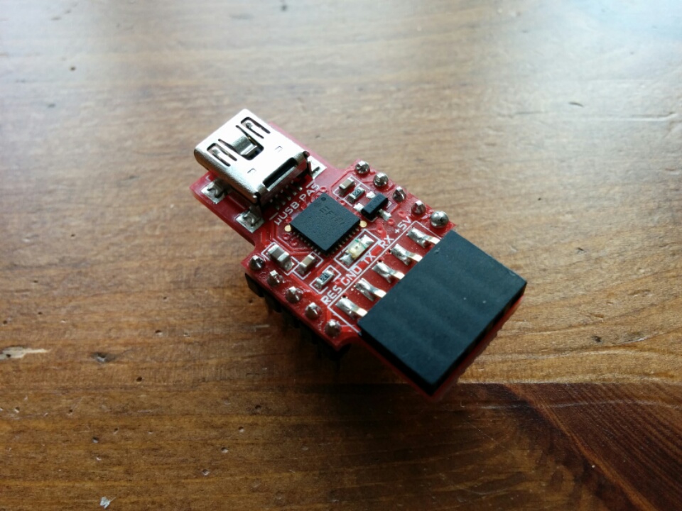
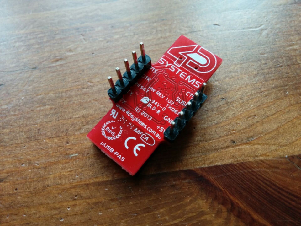
A – FTDI FT232RQ (4D Systems uUSB-PA5 Adapter, available here)
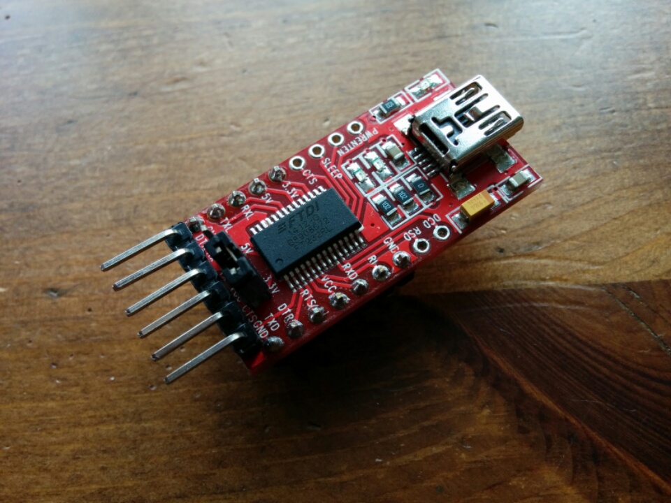
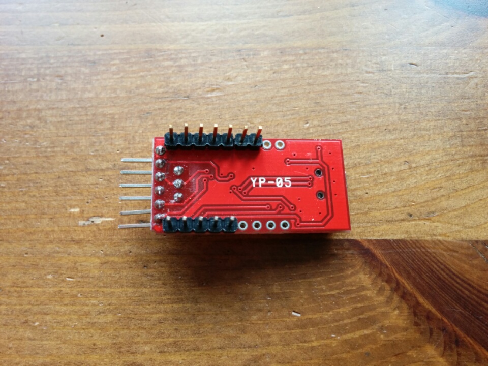
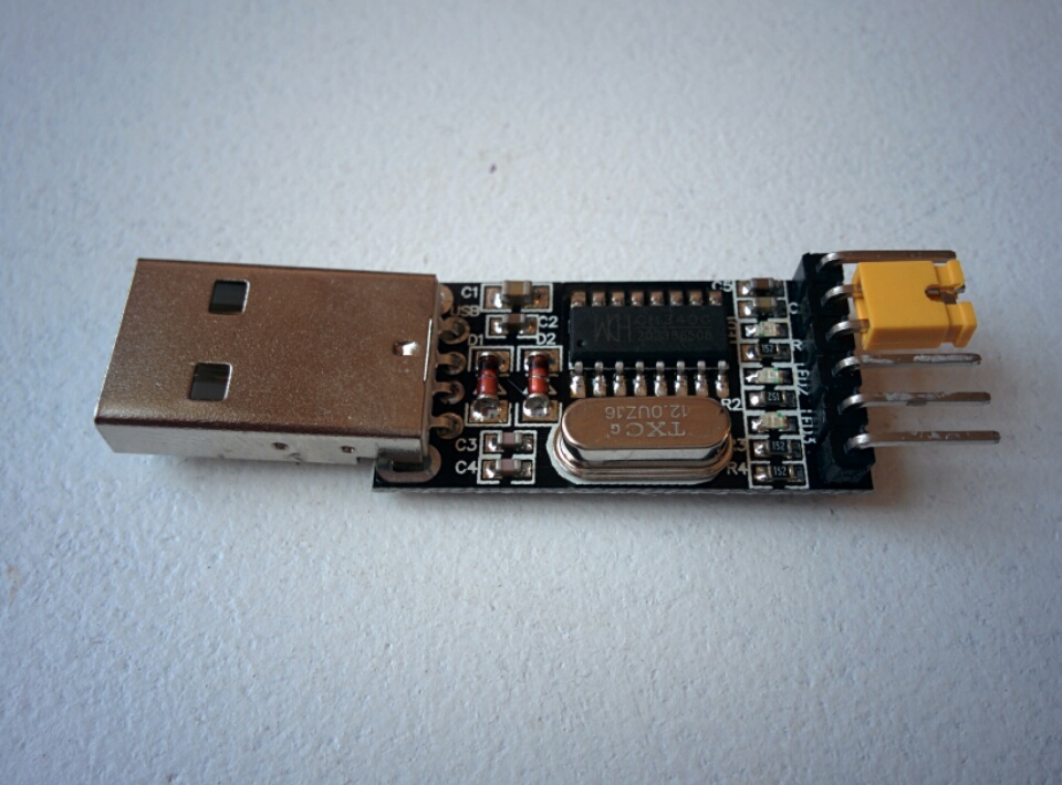
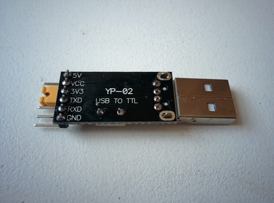
B – FTDI FT232RL (Chinese YP-05 counterfeit, from eBay)
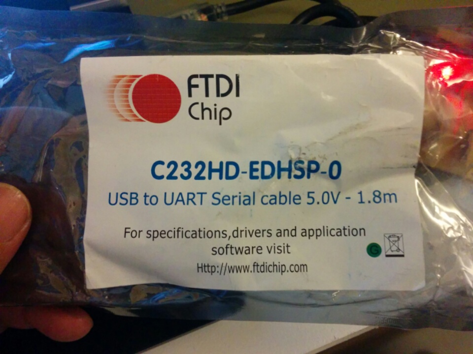
C – FTDI FT232H (genuine C232HD-EDHSP-0 cable, available here)
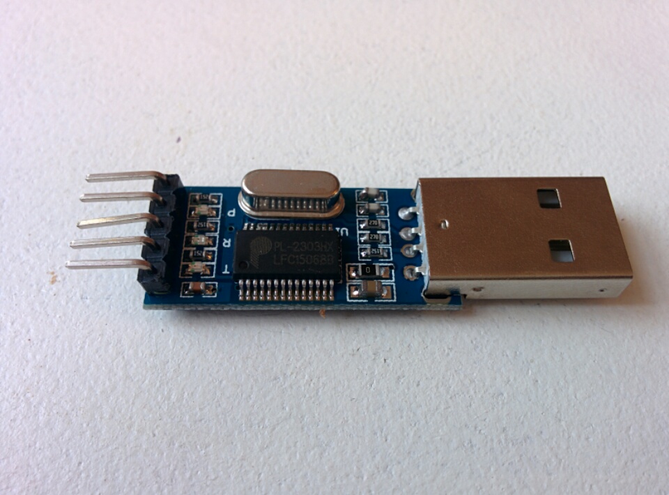
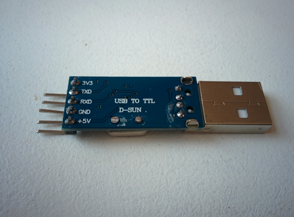
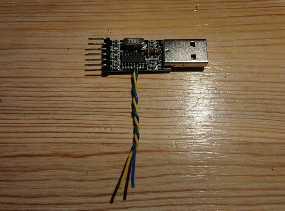
D – Prolific PL2303HX (probably counterfeit, from eBay)
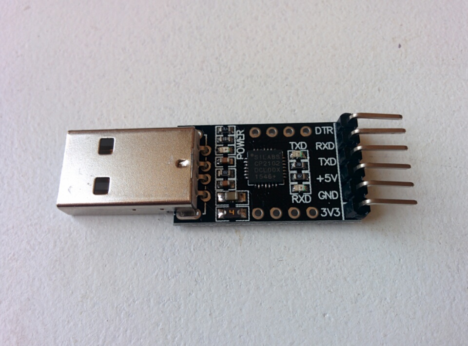
E – Silicon Labs CP2102 (black PCB, from eBay)
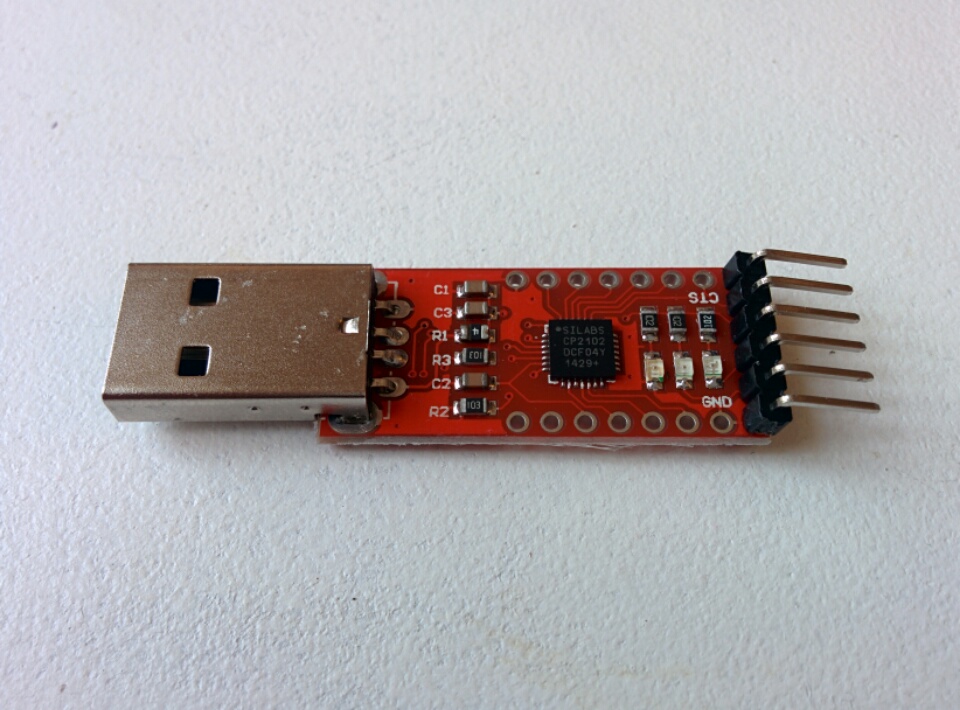
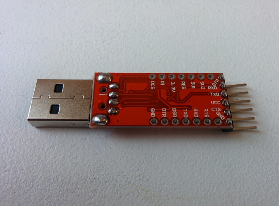
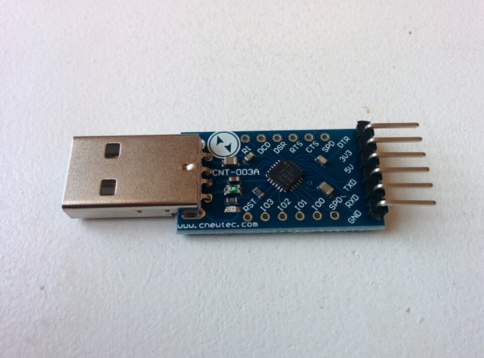
F – Silicon Labs CP2102 (red PCB, from eBay)
G – Silicon Labs CP2104 (blue PCB, from eBay)
H – WinChipHead CH340G (from eBay)
If there are any modules I’ve missed, or you think I should test, feel free to drop me a line with a link to where I can buy one. (Or you could send me one, I’d be happy.)
Also feel free to drop me any questions you might have about getting set up with the esp8266, I’ve got way more brain damage learning how to do this myself, so perhaps I could share some of it with you!
tl;dr
Buy either an adapter with a genuine FTDI chip, or one of the Silicon Labs CP2102 chips.
Test Results
Here are the results when testing the adapters at various baud rates with the following modules:
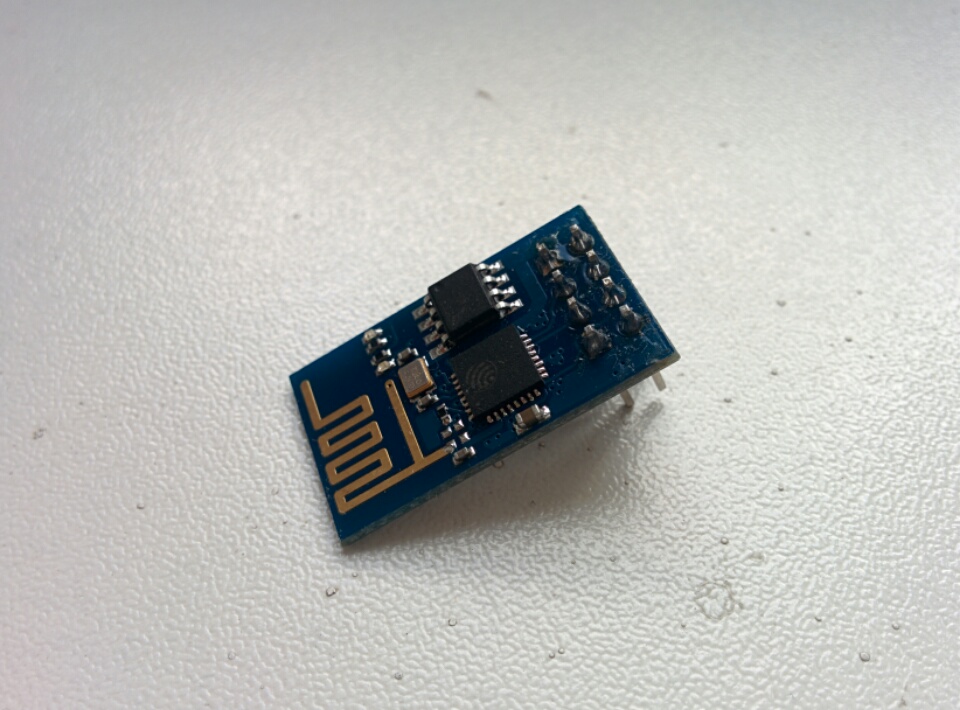
ESP-01 (4Mbit, 25Q41BT, blue PCB)
| Adapter | 3M | 1.5M | 921.6 | 460.8 | 230.4 | 115.2 | Log |
|---|---|---|---|---|---|---|---|
| A | ✓ | ✓ | ✓ | ✓ | ✓ | ✓ | link |
| B | ✗ | ✗ | ✗ | ✗ | ✗ | ✗ | |
| C | ✓ | ✓ | ✓ | ✓ | ✓ | ✓ | link |
| D | ✗ | ✗ | ✗ | ✗ | ✗ | ✗ | link |
| E | ✗ | ✓ | ✓ | ✓ | ✓ | ✓ | link |
| F | ✗ | ✓ | ✓ | ✓ | ✓ | ✓ | link |
| G | ✗ | ✓ | ✓ | ✓ | ✓ | ✓ | link |
| H | ✗ | ✗ | ✗ | ✗ | ✗ | ✓ | link |
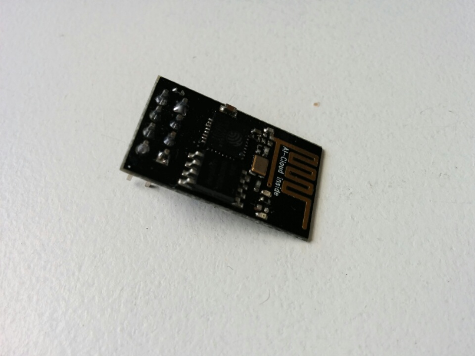
ESP-01 (8Mbit, BergMicro 25Q80A, black PCB)
| Adapter | 3M | 1.5M | 921.6 | 460.8 | 230.4 | 115.2 | Log |
|---|---|---|---|---|---|---|---|
| A | ✓ | ✓ | ✓ | ✓ | ✓ | ✓ | link |
| B | ✗ | ✗ | ✗ | ✗ | ✗ | ✗ | |
| C | ✓ | ✓ | ✓ | ✓ | ✓ | ✓ | link |
| D | ✓ | ✗ | ✗ | ✗ | ✗ | ✗ | link |
| E | ✗ | ✓ | ✓ | ✓ | ✓ | ✓ | link |
| F | ✗ | ✓ | ✓ | ✓ | ✓ | ✓ | link |
| G | ✗ | ✓ | ✓ | ✓ | ✓ | ✓ | link |
| H | ✗ | ✗ | ✗ | ✗ | ✗ | ✓ | link |
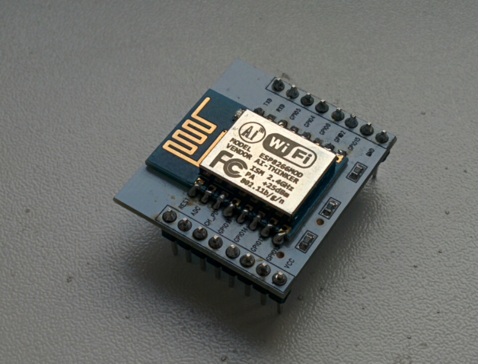
ESP-12 (32Mbit, flash_id e0 / 4016, blue PCB)
| Adapter | 3M | 1.5M | 921.6 | 460.8 | 230.4 | 115.2 | Log |
|---|---|---|---|---|---|---|---|
| A | ✓ | ✓ | ✓ | ✓ | ✓ | ✓ | link |
| B | ✗ | ✗ | ✗ | ✗ | ✗ | ✗ | link |
| C | ✓ | ✓ | ✓ | ✓ | ✓ | ✓ | link |
| D | ✗ | ✗ | ✗ | ✗ | ✗ | ✗ | link |
| E | ✗ | ✓ | ✓ | ✓ | ✓ | ✓ | link |
| F | ✗ | ✓ | ✓ | ✓ | ✓ | ✓ | link |
| G | ✗ | ✓ | ✓ | ✓ | ✓ | ✓ | link |
| H | ✗ | ✗ | ✗ | ✗ | ✗ | ✓ | link |
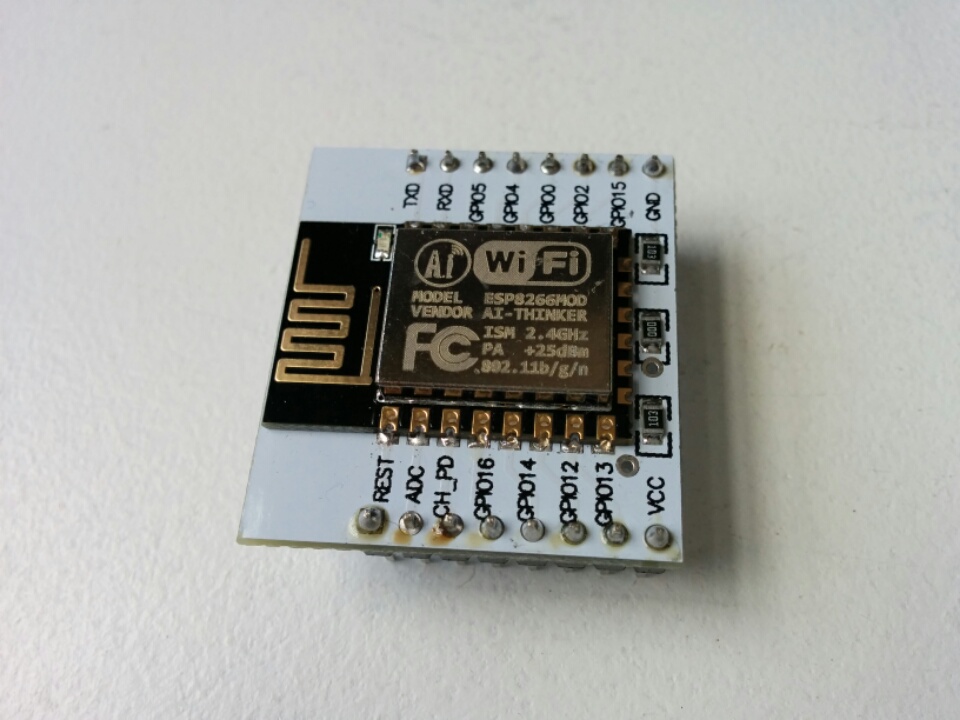
ESP-12E (32Mbit, flash_id e0 / 4016, black PCB)
| Adapter | 3M | 1.5M | 921.6 | 460.8 | 230.4 | 115.2 | Log |
|---|---|---|---|---|---|---|---|
| A | ✓ | ✓ | ✓ | ✓ | ✓ | ✓ | link |
| B | ✗ | ✗ | ✗ | ✗ | ✗ | ✗ | |
| C | ✓ | ✓ | ✓ | ✓ | ✓ | ✓ | link |
| D | ✓ | ✗ | ✗ | ✗ | ✗ | ✗ | link |
| E | ✗ | ✓ | ✓ | ✓ | ✓ | ✓ | link |
| F | ✗ | ✓ | ✓ | ✓ | ✓ | ✓ | link |
| G | ✗ | ✓ | ✓ | ✓ | ✓ | ✓ | link |
| H | ✗ | ✗ | ✗ | ✗ | ✗ | ✓ | link |
Pin Voltages When Idle
| Adapter | Vcc | DTR | RTS | TX | RX |
|---|---|---|---|---|---|
| A | 5.10 | 3.44 | 3.44 | 1.66 | 1.49 |
| B | 5.10 | 0.00 | 3.53 | 3.53 | 0.00 |
| C | 5.09 | 3.32 | 3.32 | 3.32 | 2.43 |
| D | 5.11 | 3.46 | 3.46 | 3.46 | 2.14 |
| E | 5.10 | 3.37 | 3.37 | 3.37 | 3.28 |
| F | 5.09 | 3.37 | 3.37 | 3.37 | 3.53 |
| G | 5.10 | 2.25 | 3.41 | 3.41 | 3.15 |
| H | 5.11 | 3.70 | 3.70 | 3.70 | 3.63 |
Test Setup
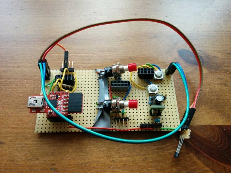
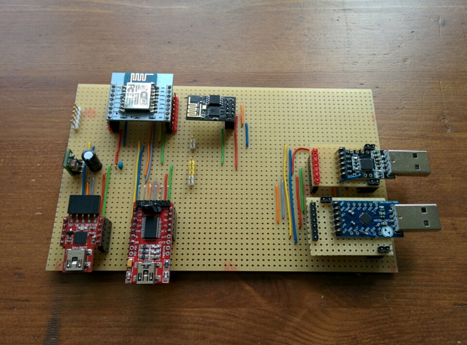
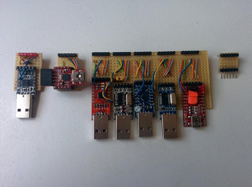
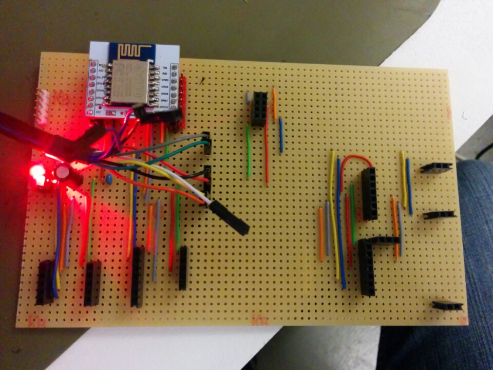
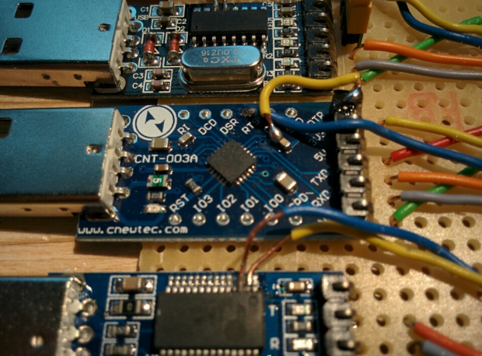
Here are the perfboards I built to program the modules:
Version 0
Only works with the 4D Systems uUSB-PA5 Adapter. Two other programming circuits on board require manual reset/mode selection and do not work.
Version 1
Version 2
Improved upon Version 1, by making a common header layout for programming: 5V (red), GND (green), DTR (yellow), RTS (blue), TX (orange), RX (gray).
The trace wires are shorter and more uniform this way, and there’s less chance of screwing up the adaptation wiring. Also, the adapters all become interchangeable, which improves test consistency.
Test Script
I’ve created a test script to test each USB adapter, using a variety of baud rates. The code is on Github here.
FTDI FT232RQ (4D Systems uUSB-PA5 Adapter)
Works.
FTDI FT232RL (Chinese counterfeit)
Does not work.
Markings on the board call it a YP-05. You can get these for about 3 EUR on eBay, and they work reasonably well as plain USB serial adapters. But they always fail for me while programming the esp8266, with the following errors:
$ ./esptool.py write_flash 0x00000 x.bin
Connecting...
Erasing flash...
Took 2.21s to erase flash block
Writing at 0x00008000... (7 %)
A fatal error occurred: Invalid head of packet
and:
esptool.py v1.0.2-dev Traceback (most recent call last): File "./esptool.py", line 1213, inmain() File "./esptool.py", line 1122, in main esp = ESPROM(args.port, initial_baud) File "./esptool.py", line 70, in __init__ self._port = serial.Serial(port) File "/usr/local/lib/python2.7/dist-packages/serial/serialutil.py", line 180, in __init__ self.open() File "/usr/local/lib/python2.7/dist-packages/serial/serialposix.py", line 311, in open self._update_dtr_state() File "/usr/local/lib/python2.7/dist-packages/serial/serialposix.py", line 605, in _update_dtr_state fcntl.ioctl(self.fd, TIOCMBIS, TIOCM_DTR_str) IOError: [Errno 5] Input/output error
The esptool programmer always stops flashing at some percentage point.
FTDI FT232H Cable (C232HD-EDHSP-0)
Works.
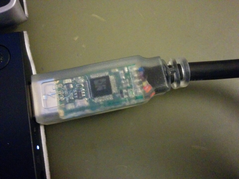
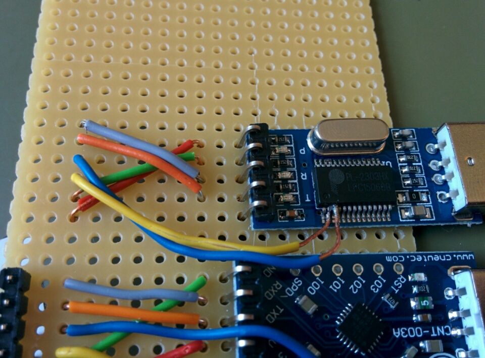
Prolific PL2303HX
Works, sometimes.
I honestly did not expect them to. Hilariously, these come shrink wrapped in plastic, because the USB plug support posts aren’t even soldered!
These are probably counterfeit chips, too, but who knows? Also, they don’t really work in Windows, after Prolific disabled support for counterfeit devices (though sometimes I wonder how they even know).
Thanks to Daniel for soldering the DTR and RTS wires onto the extremely thin SSOP pins. For great justice!
[30217.752502] usb 3-1.4: new full-speed USB device number 32 using ehci-pci
[30217.845449] usb 3-1.4: New USB device found, idVendor=067b, idProduct=2303
[30217.845454] usb 3-1.4: New USB device strings: Mfr=1, Product=2, SerialNumber=0
[30217.845457] usb 3-1.4: Product: USB-Serial Controller
[30217.845459] usb 3-1.4: Manufacturer: Prolific Technology Inc.
[30217.845884] pl2303 3-1.4:1.0: pl2303 converter detected
[30217.847596] usb 3-1.4: pl2303 converter now attached to ttyUSB1
Bus 003 Device 032: ID 067b:2303 Prolific Technology, Inc. PL2303 Serial Port
$ ./esptool.py read_mac
esptool.py v1.0.2-dev
Connecting...
MAC: 5c:cf:7f:07:8e:cd

$ ./esptool.py chip_id
esptool.py v1.0.2-dev
Connecting...
Chip ID: 0x00078ecd

$ ./esptool.py flash_id
esptool.py v1.0.2-dev
Connecting...
Manufacturer: e0
Device: 4016

$ ./esptool.py read_flash 0x0 0x80000 x.bin
esptool.py v1.0.2-dev
Connecting...
Running Cesanta flasher stub...
Reading 524288 @ 0x0... 524288 (100 %)
Read 524288 bytes at 0x0 in 49.9 seconds (84.0 kbit/s)...

$ ./esptool.py write_flash 0x0 x.bin
esptool.py v1.0.2-dev
Connecting...
Running Cesanta flasher stub...
Flash params set to 0x0000
Writing 524288 @ 0x0... 524288 (100 %)
Wrote 524288 bytes at 0x0 in 46.1 seconds (90.9 kbit/s)...
Leaving...
Silicon Labs CP2102 (black PCB)
Works.
Silicon Labs CP2102 (red PCB)
Works.
[ 7727.919777] usb 2-1: new full-speed USB device number 4 using xhci_hcd
[ 7728.049611] usb 2-1: New USB device found, idVendor=10c4, idProduct=ea60
[ 7728.049616] usb 2-1: New USB device strings: Mfr=1, Product=2, SerialNumber=3
[ 7728.049619] usb 2-1: Product: CP2102 USB to UART Bridge Controller
[ 7728.049621] usb 2-1: Manufacturer: Silicon Labs
[ 7728.049623] usb 2-1: SerialNumber: 0001
[ 7729.078772] usbcore: registered new interface driver usbserial
[ 7729.078985] usbcore: registered new interface driver usbserial_generic
[ 7729.079148] usbserial: USB Serial support registered for generic
[ 7729.083795] usbcore: registered new interface driver cp210x
[ 7729.083830] usbserial: USB Serial support registered for cp210x
[ 7729.083862] cp210x 2-1:1.0: cp210x converter detected
[ 7729.084803] usb 2-1: cp210x converter now attached to ttyUSB0
Bus 002 Device 007: ID 10c4:ea60 Cygnal Integrated Products, Inc. CP210x UART Bridge / myAVR mySmartUSB light
$ ./esptool.py read_flash 0x0 0x80000 x.bin
esptool.py v1.0.2-dev
Connecting...
Running Cesanta flasher stub...
Reading 524288 @ 0x0... 524288 (100 %)
Read 524288 bytes at 0x0 in 60.8 seconds (69.0 kbit/s)...

$ ./esptool.py write_flash 0x0 x.bin
esptool.py v1.0.2-dev
Connecting...
Running Cesanta flasher stub...
Flash params set to 0x0000
Writing 524288 @ 0x0... 524288 (100 %)
Wrote 524288 bytes at 0x0 in 45.5 seconds (92.3 kbit/s)...
Leaving...
Silicon Labs CP2104 (blue PCB)
Works!
After modifying the DTR line to bypass the capacitor as suggested by comments from 0xPIT, this adapter works as expected.
Doesn’t work.
Persistent errors on DTR line:
$ python esptool.py --port /dev/ttyUSB0 chip_id esptool.py v1.0.2-dev Connecting... Traceback (most recent call last): File "esptool.py", line 1214, inmain() File "esptool.py", line 1124, in main esp.connect() File "esptool.py", line 159, in connect self._port.setDTR(False) File "/usr/local/lib/python2.7/dist-packages/serial/serialutil.py", line 547, in setDTR self.dtr = value File "/usr/local/lib/python2.7/dist-packages/serial/serialutil.py", line 411, in dtr self._update_dtr_state() File "/usr/local/lib/python2.7/dist-packages/serial/serialposix.py", line 607, in _update_dtr_state fcntl.ioctl(self.fd, TIOCMBIC, TIOCM_DTR_str) IOError: [Errno 5] Input/output error $ python esptool.py --port /dev/ttyUSB0 chip_id esptool.py v1.0.2-dev Connecting... A fatal error occurred: Failed to connect to ESP8266 $ python esptool.py --port /dev/ttyUSB0 flash_id esptool.py v1.0.2-dev Connecting... Traceback (most recent call last): File "esptool.py", line 1214, in main() File "esptool.py", line 1124, in main esp.connect() File "esptool.py", line 159, in connect self._port.setDTR(False) File "/usr/local/lib/python2.7/dist-packages/serial/serialutil.py", line 547, in setDTR self.dtr = value File "/usr/local/lib/python2.7/dist-packages/serial/serialutil.py", line 411, in dtr self._update_dtr_state() File "/usr/local/lib/python2.7/dist-packages/serial/serialposix.py", line 607, in _update_dtr_state fcntl.ioctl(self.fd, TIOCMBIC, TIOCM_DTR_str) IOError: [Errno 5] Input/output error
[12903.595812] usb 2-1: new full-speed USB device number 12 using xhci_hcd
[12903.725411] usb 2-1: New USB device found, idVendor=10c4, idProduct=ea60
[12903.725416] usb 2-1: New USB device strings: Mfr=1, Product=2, SerialNumber=3
[12903.725418] usb 2-1: Product: CP2104 USB to UART Bridge Controller
[12903.725420] usb 2-1: Manufacturer: Silicon Labs
[12903.725422] usb 2-1: SerialNumber: 0100ACEA
[12903.726485] cp210x 2-1:1.0: cp210x converter detected
[12903.727140] usb 2-1: cp210x converter now attached to ttyUSB0
Bus 002 Device 012: ID 10c4:ea60 Cygnal Integrated Products, Inc. CP210x UART Bridge / myAVR mySmartUSB light
WinChipHead CH340G
Works!
These things are so ridiculously cheap. They’re normally covered in a shrink-wrap plastic tube, which is because the two USB support pins aren’t even soldered!
These are more work, you have to wire the DTR / RTS lines on the SOP package.
[11337.449533] usb 2-1: new full-speed USB device number 6 using xhci_hcd
[11337.578783] usb 2-1: New USB device found, idVendor=1a86, idProduct=7523
[11337.578788] usb 2-1: New USB device strings: Mfr=0, Product=2, SerialNumber=0
[11337.578790] usb 2-1: Product: USB2.0-Serial
[11338.602146] usbcore: registered new interface driver ch341
[11338.602511] usbserial: USB Serial support registered for ch341-uart
[11338.602547] ch341 2-1:1.0: ch341-uart converter detected
[11338.604752] usb 2-1: ch341-uart converter now attached to ttyUSB0
Bus 002 Device 006: ID 1a86:7523 QinHeng Electronics HL-340 USB-Serial adapter
$ ./esptool.py read_flash 0x0 0x80000 x.bin
esptool.py v1.0.2-dev
Connecting...
Running Cesanta flasher stub...
Reading 524288 @ 0x0... 524288 (100 %)
Read 524288 bytes at 0x0 in 50.8 seconds (82.5 kbit/s)...

$ ./esptool.py write_flash 0x0 x.bin
esptool.py v1.0.2-dev
Connecting...
Running Cesanta flasher stub...
Flash params set to 0x0000
Writing 524288 @ 0x0... 524288 (100 %)
Wrote 524288 bytes at 0x0 in 45.5 seconds (92.3 kbit/s)...
Leaving...

awesome. you helped me figure out why write_flash always stopped at 7%. linked to you in my blog post https://medium.com/bonus-thoughts/getting-started-with-the-esp8266-a94a85de5174#.s8d5m0k0e
Thanks for your article!
The Silicon Labs CP2104 (blue PCB) will work once you short the capacitor in the DTR line.
Nice, I will try that.
Tried shorting the DTR line, now it works like it should. Updated the article accordingly.
Thank you Thank you Thank you 🙂 Your post solved my problem. Replaced the FTDI FT232RL with the CH340G and it worked like a charm. Awesome 😀
Google should show this post in the top of their search list results for ESP8266 flash programming.
Thanks for you study. You have revived my hope. My error doesn’t seem to show up in your testing, however. I have spent way too many hours trying to figure this out. Any chance you know what’s going on here:
Clinic:~ fed$ esptool.py –baud 115200 –port /dev/tty.usbserial-A50285BI flash_id
esptool.py v1.3-dev
Connecting…
Manufacturer: e0
Device: 4014
Clinic:~ fed$ esptool.py –baud 115200 –port /dev/tty.usbserial-A50285BI chip_id
esptool.py v1.3-dev
Connecting…
Chip ID: 0x001eb645
Clinic:~ fed$ esptool.py –baud 115200 –port /dev/tty.usbserial-A50285BI read_mac
esptool.py v1.3-dev
Connecting…
MAC: 5c:cf:7f:1e:b6:45
Clinic:~ fed$ esptool.py –baud 115200 –port /dev/tty.usbserial-A50285BI erase_flash
esptool.py v1.3-dev
Connecting…
Running Cesanta flasher stub…
A fatal error occurred: Timed out waiting for packet header
What kind of USB-to-serial adapter are you using? Looks like it could be one of the bad counterfeits? For the amount of time I ended up burning on this problem, the slightly higher cost of a genuine FTDI cable or one of the SiLabs CP210x cables was worth it.
Have you tried this: https://www.itead.cc/foca-pro.html
This comes with CP2102.
However doesnt work for me with a black ESP-01. :S
Hmm. What kind of errors is esptool giving?
I have a black ESP-01 and a Silicon Labs CP2102 (black PCB, from eBay). I tried the CP2102 (black) after having lot of problems with the FTDI (i have now a nice collection and only 1 of them works with the ESP modules).
This CP2102 doesn’t work at all.
Same error than the FTDI: invalid packet
MEMORY START
ELSE…. 26
Invalid head of packet (”)
Exception in thread Thread-6:
Traceback (most recent call last):
File “threading.pyo”, line 801, in __bootstrap_inner
File “download_panel_info.pyo”, line 785, in run
File “esptool_api.pyo”, line 763, in flash_download_thread
File “esptool_api.pyo”, line 1761, in __init__
File “esptool_api.pyo”, line 1646, in read_packet
Exception: Invalid head of packet (”)
I guess the problems are the serial modules, with counterfeit, mal functioning circuits or bad design, because when I use the good FTDI no problem at all.
Are these legitimate FTDI cables, like one of these? If not, then there’s no guarantee here. Only the legitimate FTDI cable, or one of the adapter boards with a legit FTDI chip, worked as the gold standard for me.
But I’m surprised the CP210x chips aren’t working for you, as I had pretty good luck with them. Perhaps someone’s built a cheap counterfeit, or like you mention, maybe there’s a new version of the PCB, which has some kind of design flaw. Only thing to do in this case is to probably just buy other models and see if they work, unfortunately.
Alo.
All the FTDI and CP2102 are from eBay.The only FTDI (also from ebay) that works, was bought years ago.
It looks the FTDI modules are getting worse over the time, because I have a chronology of them and they present more problems until a recent one was a counterfeit part (driver showing “not genuine”). Then I moved to the CP2102 (well I try xDD). I don’t need to program at high speeds just programming is enough.
The point with the FTDI is they work fine with 115k in AT mode (even high rates) but they don’t when programing. I also realised recently the some modules corrupt data: I was testing a personal project sending data at 115k but with a very high rate (dozen of ms as much) and then I realised some data, randomly, was corrupted (“then” was about 1 week of headaches because software logic was perfect, so, why the results are wrong?!). So the problem looks related to the speed and the rate of transmission. buffer corruption? dunno.
About the CP2102 I thought it could be a counterfeit or some problem with the PCB but I don’t have tools to check this. The tools from the official manufacturer work, but I noticed that if you try to change the assigned serial com in the module, it never gets the number you wants. It says it was programmed but when enumerating Windows assigns one different. Not sure if it’s normal or not. Without proper tools it’s hard to check anything.
Visual inspection reports the module shown in your site and mine has only a visible difference: the PPTC. Mine has a 000 resistor instead. It shouldn’t be a problem but if you find a difference here, there can be more hidden.
Hello, I use Prolific PL2303HX for ESP-01. It works to run AT commands from terminal but it didn’t work when I tried esptool.py command just to check flsh_id, chip_id, etc. Do you have any idea about the problem?
My terminal configuration use baud 115200 at COM7. For AT+GMR it results:
AT+GMR
AT version:1.2.0.0(Jul 1 2016 20:04:45)
SDK version:1.5.4.1(39cb9a32)
Ai-Thinker Technology Co. Ltd.
Dec 2 2016 14:21:16
OK
but when I use esptool.py like this:
$ esptool.py –port COM7 –baud 115200 flash_id
it results:
esptool.py v2.0.1
Connecting…….._____….._____….._____….._____….._____….._____….._____….._____….._____….._____
A fatal error occurred: Failed to connect to Espressif device: Timed out waiting for packet header
Do you have the DTR and RTS lines hooked into the CH_PD and RESET pins on the ESP-01 needed to trigger a reset of the device?
If no, then that’s what you’d have to do. I don’t remember which one goes to which, but it’s easy enough to try and swap.
If yes, then you would need to try a different USB to serial adapter.