It’s not you, it’s the crappy counterfeit FTDI chip in your USB to serial adapter. That is what is keeping your esptool.py or esptool-ck flash download from working.
When I first started using the esp8266, I had some serious problems getting esptool.py and esptool-ck working, due to one model of super-flaky, cheap USB serial adapter not working.
This had me tearing my hair out for a few weeks, as I tried replacing everything besides the serial adapter, which I had assumed could not possibly be the culprit.
After all, USB-to-serial conversion is a solved problem, right?
Wrong.
This page is a collection of reviews of the serial adapters I’ve used, which specifically have support for the DTR / RTS signaling used to automatically reset the esp8266 and put the chip into UART firmware download mode.
Here are the adapters I’ve tried:
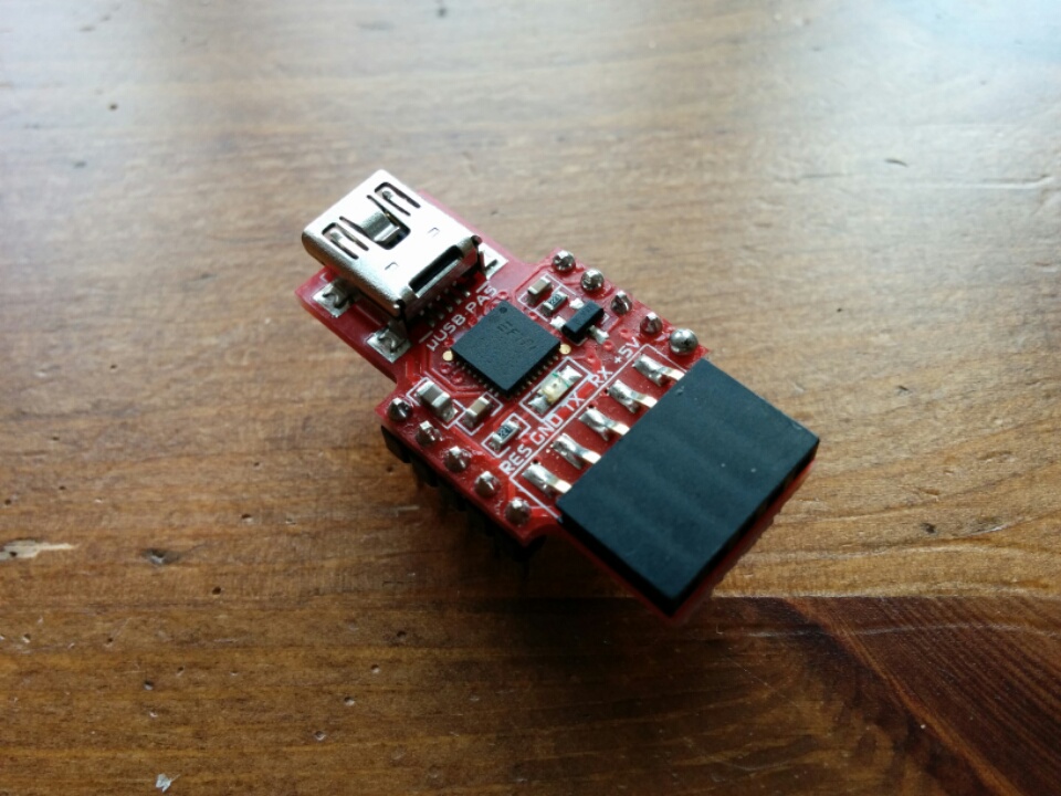
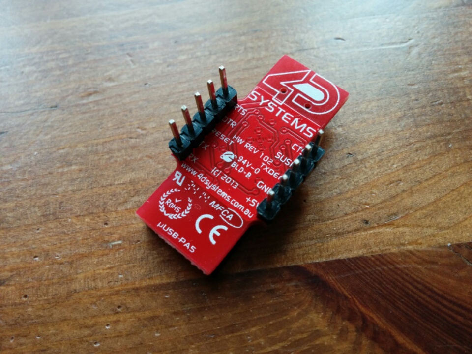
A – FTDI FT232RQ (4D Systems uUSB-PA5 Adapter, available here)
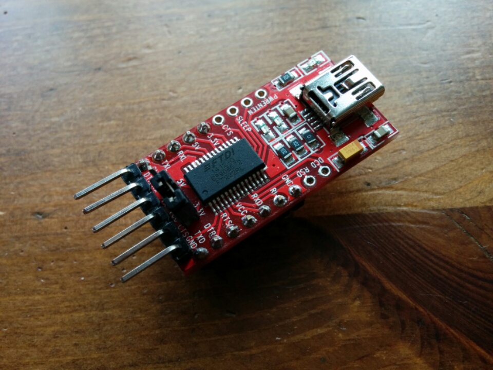
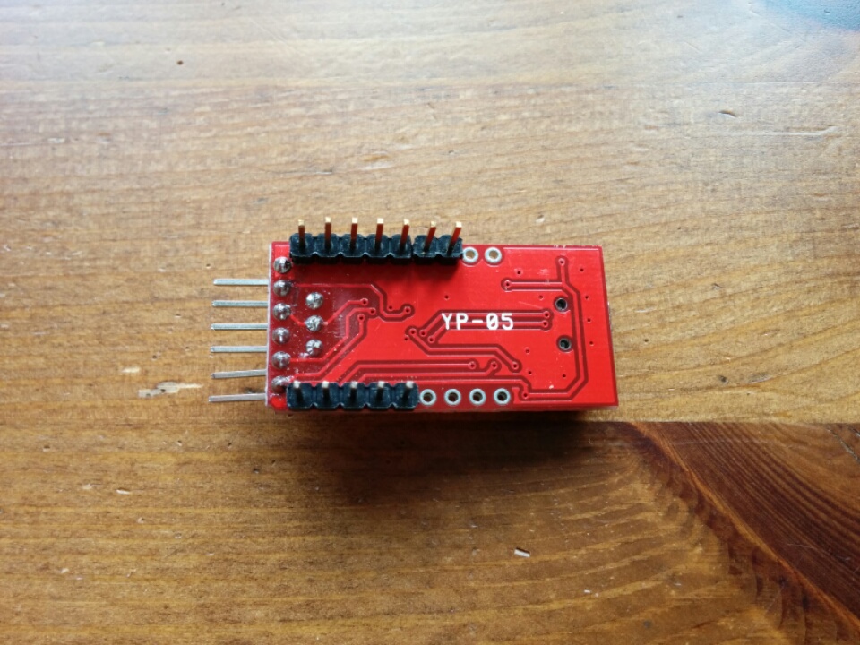
B – FTDI FT232RL (Chinese YP-05 counterfeit, from eBay)
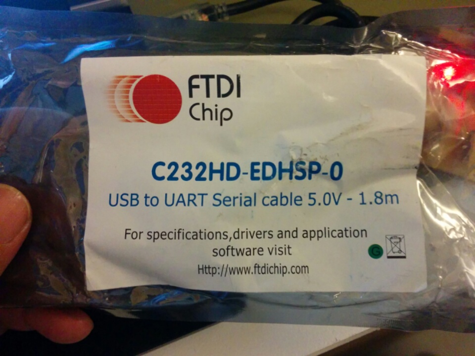
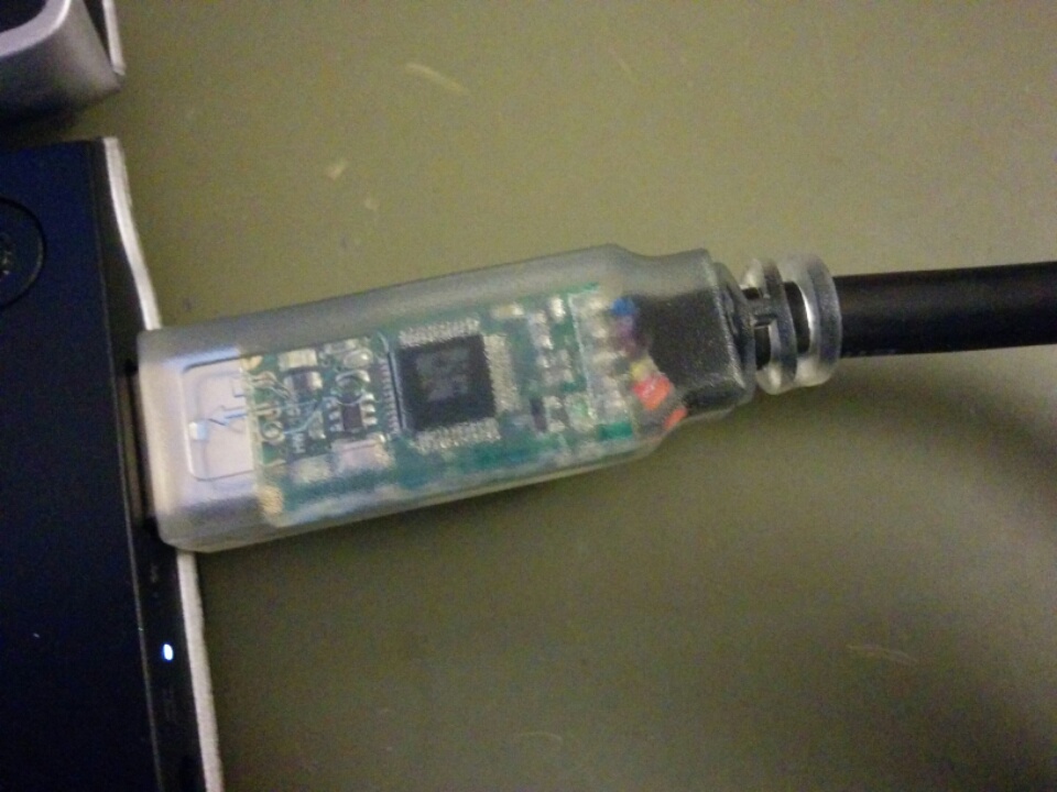
C – FTDI FT232H (genuine C232HD-EDHSP-0 cable, available here)
D – Prolific PL2303HX (probably counterfeit, from eBay)
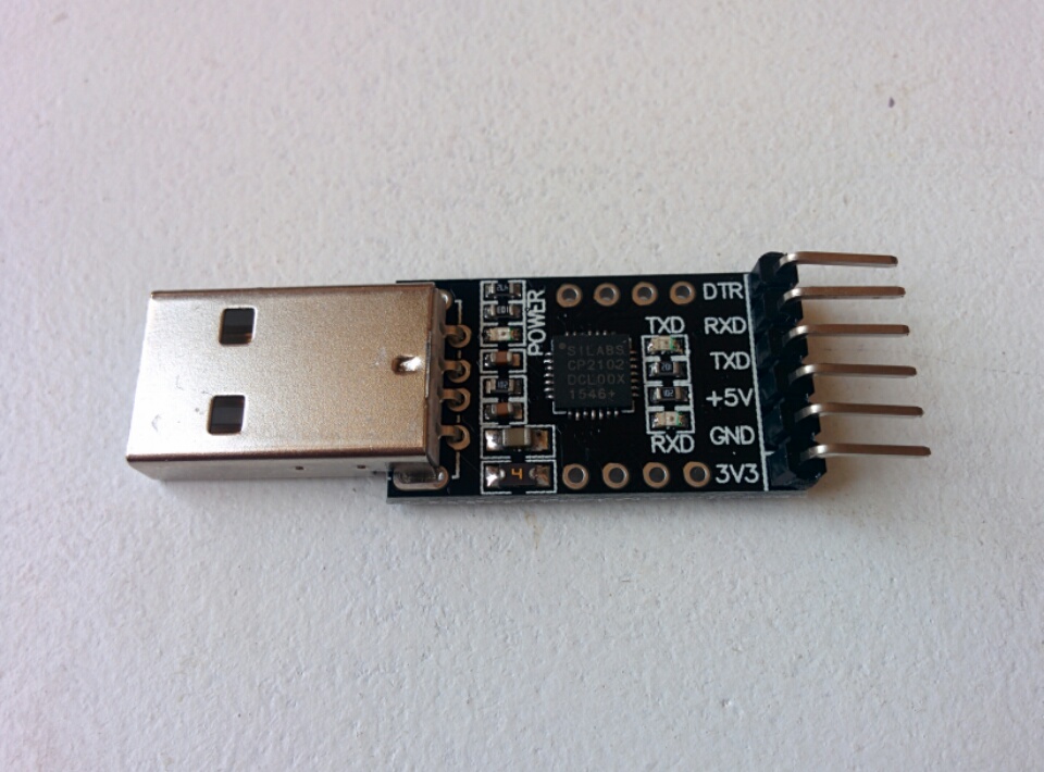
E – Silicon Labs CP2102 (black PCB, from eBay)
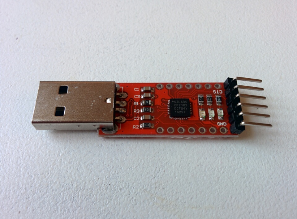
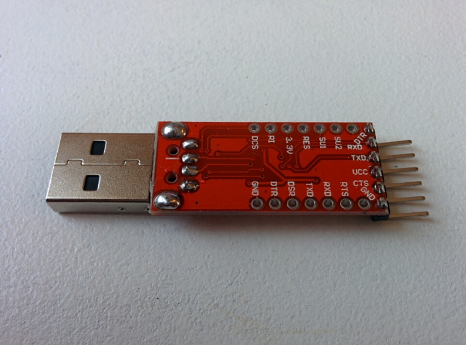
F – Silicon Labs CP2102 (red PCB, from eBay)
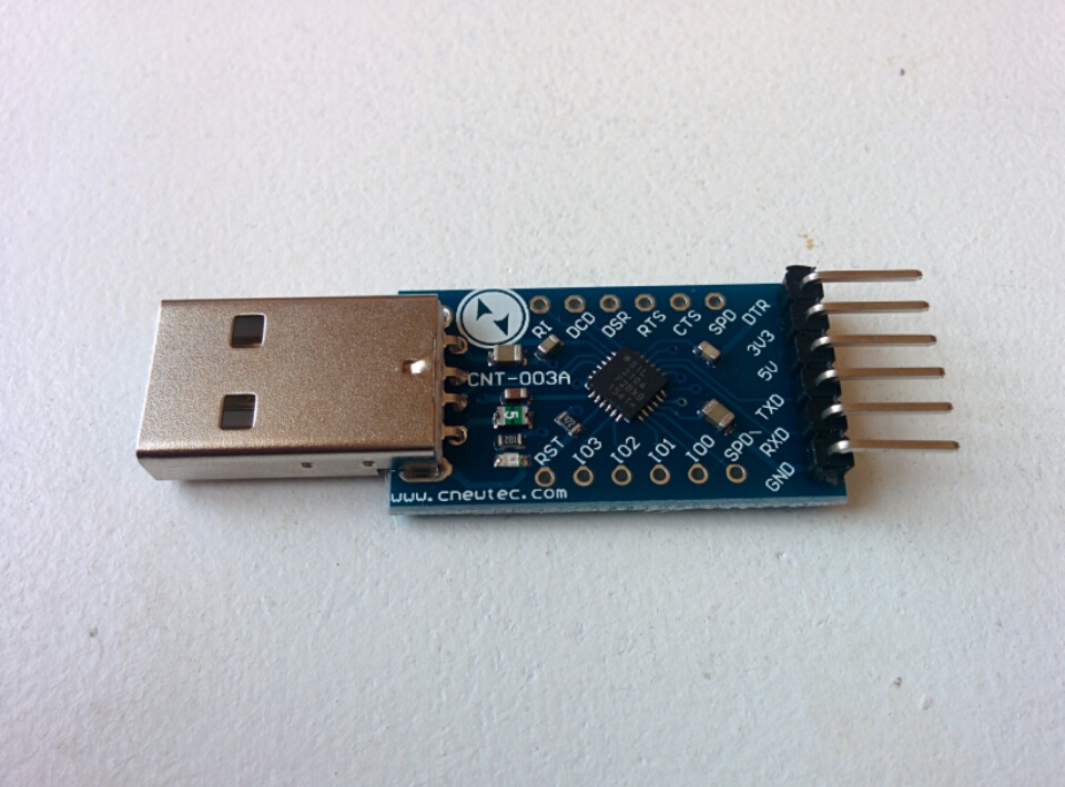
G – Silicon Labs CP2104 (blue PCB, from eBay)
H – WinChipHead CH340G (from eBay)
If there are any modules I’ve missed, or you think I should test, feel free to drop me a line with a link to where I can buy one. (Or you could send me one, I’d be happy.)
Also feel free to drop me any questions you might have about getting set up with the esp8266, I’ve got way more brain damage learning how to do this myself, so perhaps I could share some of it with you!
tl;dr
Buy either an adapter with a genuine FTDI chip, or one of the Silicon Labs CP2102 chips.
Test Results
Here are the results when testing the adapters at various baud rates with the following modules:
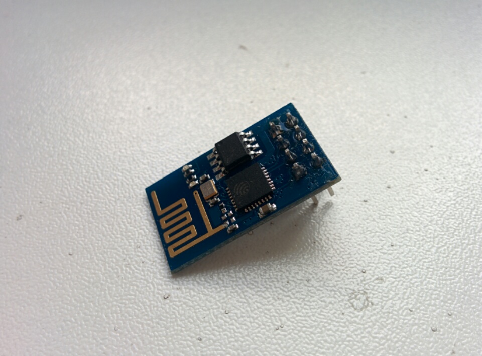
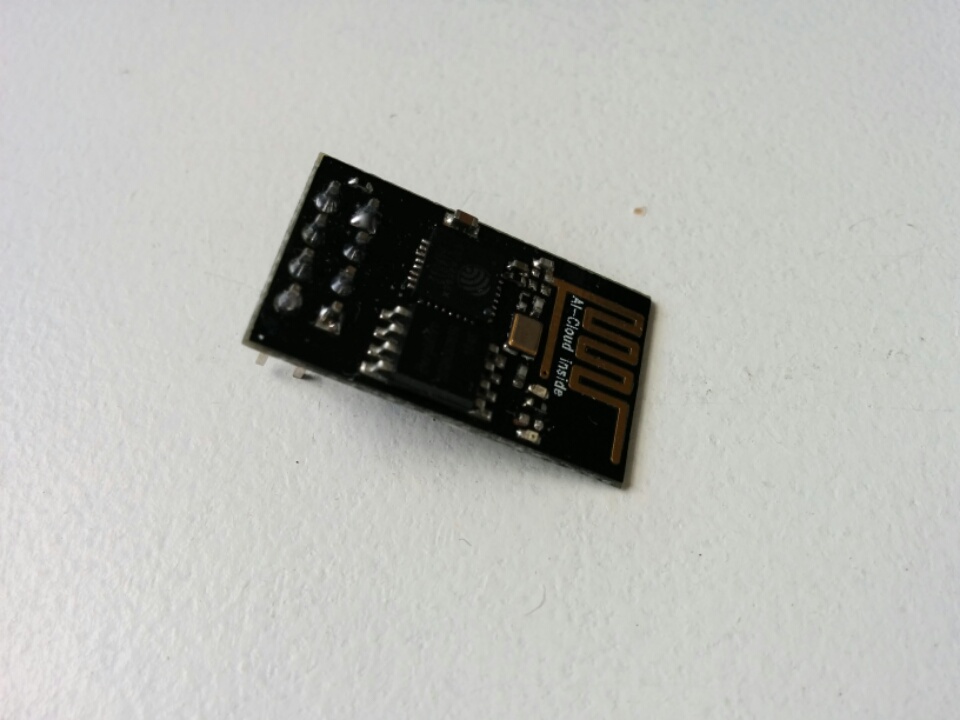
ESP-01 (4Mbit, 25Q41BT, blue PCB)
| Adapter | 3M | 1.5M | 921.6 | 460.8 | 230.4 | 115.2 | Log |
|---|---|---|---|---|---|---|---|
| A | ✓ | ✓ | ✓ | ✓ | ✓ | ✓ | link |
| B | ✗ | ✗ | ✗ | ✗ | ✗ | ✗ | |
| C | ✓ | ✓ | ✓ | ✓ | ✓ | ✓ | link |
| D | ✗ | ✗ | ✗ | ✗ | ✗ | ✗ | link |
| E | ✗ | ✓ | ✓ | ✓ | ✓ | ✓ | link |
| F | ✗ | ✓ | ✓ | ✓ | ✓ | ✓ | link |
| G | ✗ | ✓ | ✓ | ✓ | ✓ | ✓ | link |
| H | ✗ | ✗ | ✗ | ✗ | ✗ | ✓ | link |
ESP-01 (8Mbit, BergMicro 25Q80A, black PCB)
| Adapter | 3M | 1.5M | 921.6 | 460.8 | 230.4 | 115.2 | Log |
|---|---|---|---|---|---|---|---|
| A | ✓ | ✓ | ✓ | ✓ | ✓ | ✓ | link |
| B | ✗ | ✗ | ✗ | ✗ | ✗ | ✗ | |
| C | ✓ | ✓ | ✓ | ✓ | ✓ | ✓ | link |
| D | ✓ | ✗ | ✗ | ✗ | ✗ | ✗ | link |
| E | ✗ | ✓ | ✓ | ✓ | ✓ | ✓ | link |
| F | ✗ | ✓ | ✓ | ✓ | ✓ | ✓ | link |
| G | ✗ | ✓ | ✓ | ✓ | ✓ | ✓ | link |
| H | ✗ | ✗ | ✗ | ✗ | ✗ | ✓ | link |
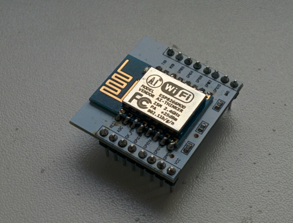
ESP-12 (32Mbit, flash_id e0 / 4016, blue PCB)
| Adapter | 3M | 1.5M | 921.6 | 460.8 | 230.4 | 115.2 | Log |
|---|---|---|---|---|---|---|---|
| A | ✓ | ✓ | ✓ | ✓ | ✓ | ✓ | link |
| B | ✗ | ✗ | ✗ | ✗ | ✗ | ✗ | link |
| C | ✓ | ✓ | ✓ | ✓ | ✓ | ✓ | link |
| D | ✗ | ✗ | ✗ | ✗ | ✗ | ✗ | link |
| E | ✗ | ✓ | ✓ | ✓ | ✓ | ✓ | link |
| F | ✗ | ✓ | ✓ | ✓ | ✓ | ✓ | link |
| G | ✗ | ✓ | ✓ | ✓ | ✓ | ✓ | link |
| H | ✗ | ✗ | ✗ | ✗ | ✗ | ✓ | link |
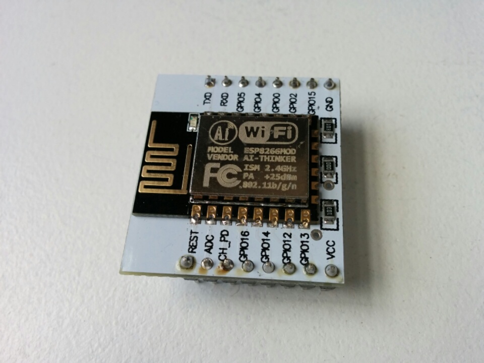
ESP-12E (32Mbit, flash_id e0 / 4016, black PCB)
| Adapter | 3M | 1.5M | 921.6 | 460.8 | 230.4 | 115.2 | Log |
|---|---|---|---|---|---|---|---|
| A | ✓ | ✓ | ✓ | ✓ | ✓ | ✓ | link |
| B | ✗ | ✗ | ✗ | ✗ | ✗ | ✗ | |
| C | ✓ | ✓ | ✓ | ✓ | ✓ | ✓ | link |
| D | ✓ | ✗ | ✗ | ✗ | ✗ | ✗ | link |
| E | ✗ | ✓ | ✓ | ✓ | ✓ | ✓ | link |
| F | ✗ | ✓ | ✓ | ✓ | ✓ | ✓ | link |
| G | ✗ | ✓ | ✓ | ✓ | ✓ | ✓ | link |
| H | ✗ | ✗ | ✗ | ✗ | ✗ | ✓ | link |
Pin Voltages When Idle
| Adapter | Vcc | DTR | RTS | TX | RX |
|---|---|---|---|---|---|
| A | 5.10 | 3.44 | 3.44 | 1.66 | 1.49 |
| B | 5.10 | 0.00 | 3.53 | 3.53 | 0.00 |
| C | 5.09 | 3.32 | 3.32 | 3.32 | 2.43 |
| D | 5.11 | 3.46 | 3.46 | 3.46 | 2.14 |
| E | 5.10 | 3.37 | 3.37 | 3.37 | 3.28 |
| F | 5.09 | 3.37 | 3.37 | 3.37 | 3.53 |
| G | 5.10 | 2.25 | 3.41 | 3.41 | 3.15 |
| H | 5.11 | 3.70 | 3.70 | 3.70 | 3.63 |
Test Setup
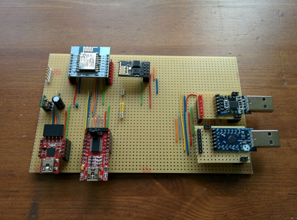
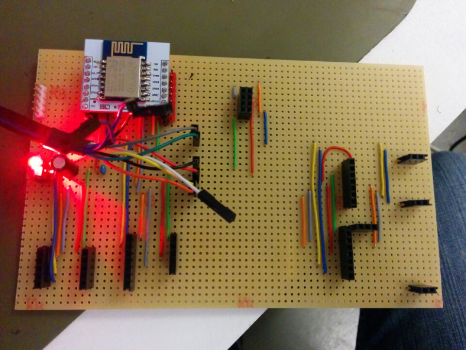
Here are the perfboards I built to program the modules:
Version 0
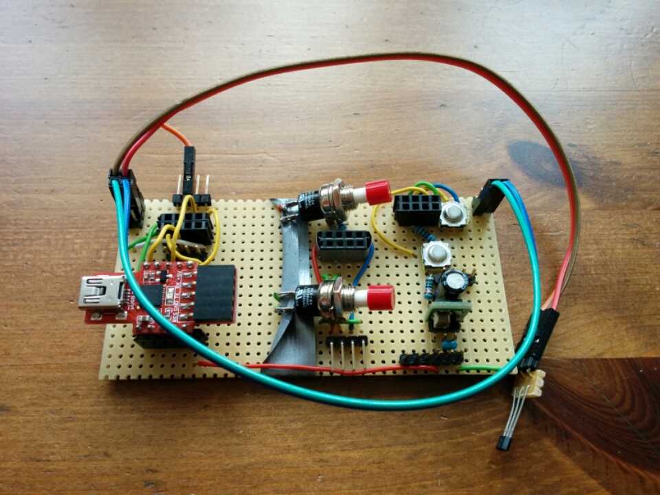
Only works with the 4D Systems uUSB-PA5 Adapter. Two other programming circuits on board require manual reset/mode selection and do not work.
Version 1
Version 2
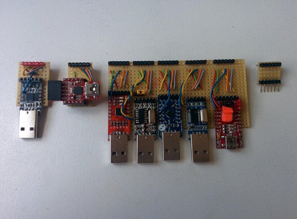
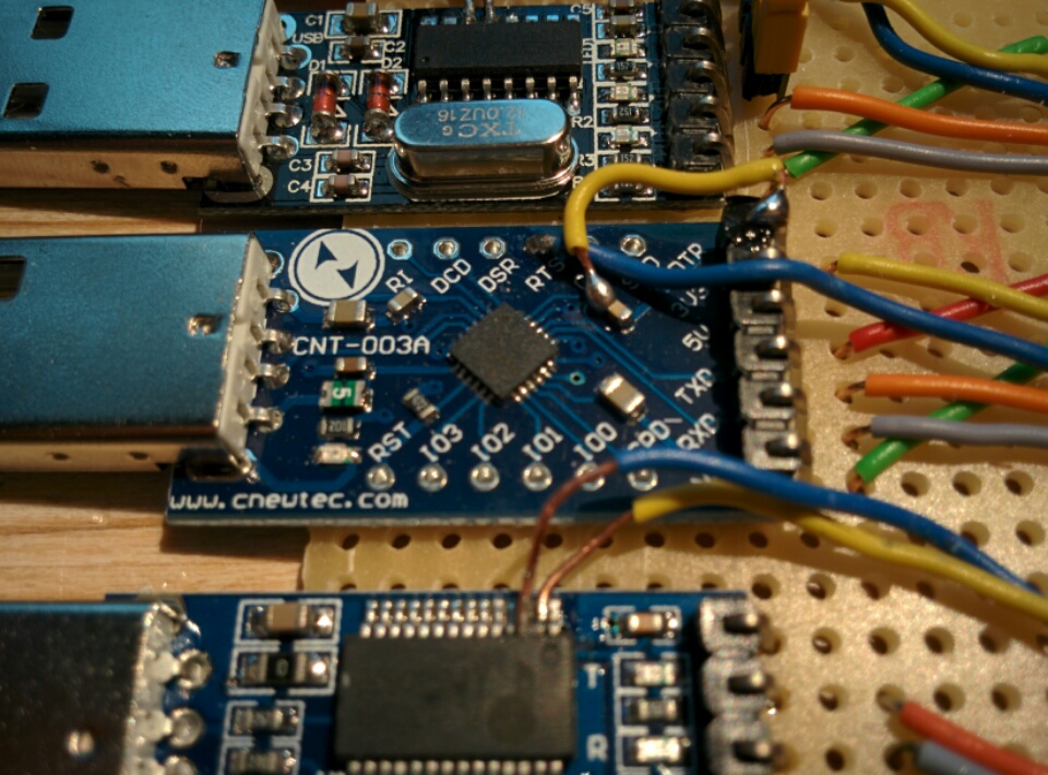
Improved upon Version 1, by making a common header layout for programming: 5V (red), GND (green), DTR (yellow), RTS (blue), TX (orange), RX (gray).
The trace wires are shorter and more uniform this way, and there’s less chance of screwing up the adaptation wiring. Also, the adapters all become interchangeable, which improves test consistency.
Test Script
I’ve created a test script to test each USB adapter, using a variety of baud rates. The code is on Github here.
FTDI FT232RQ (4D Systems uUSB-PA5 Adapter)
Works.
FTDI FT232RL (Chinese counterfeit)
Does not work.
Markings on the board call it a YP-05. You can get these for about 3 EUR on eBay, and they work reasonably well as plain USB serial adapters. But they always fail for me while programming the esp8266, with the following errors:
$ ./esptool.py write_flash 0x00000 x.bin
Connecting...
Erasing flash...
Took 2.21s to erase flash block
Writing at 0x00008000... (7 %)
A fatal error occurred: Invalid head of packet
and:
esptool.py v1.0.2-dev Traceback (most recent call last): File "./esptool.py", line 1213, inmain() File "./esptool.py", line 1122, in main esp = ESPROM(args.port, initial_baud) File "./esptool.py", line 70, in __init__ self._port = serial.Serial(port) File "/usr/local/lib/python2.7/dist-packages/serial/serialutil.py", line 180, in __init__ self.open() File "/usr/local/lib/python2.7/dist-packages/serial/serialposix.py", line 311, in open self._update_dtr_state() File "/usr/local/lib/python2.7/dist-packages/serial/serialposix.py", line 605, in _update_dtr_state fcntl.ioctl(self.fd, TIOCMBIS, TIOCM_DTR_str) IOError: [Errno 5] Input/output error
The esptool programmer always stops flashing at some percentage point.
FTDI FT232H Cable (C232HD-EDHSP-0)
Works.
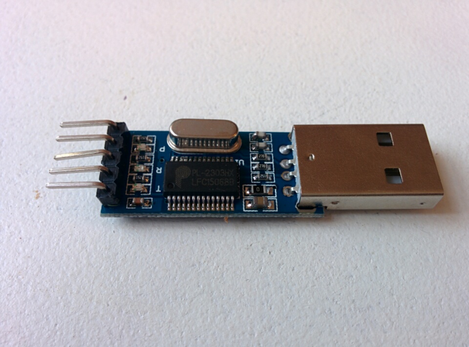
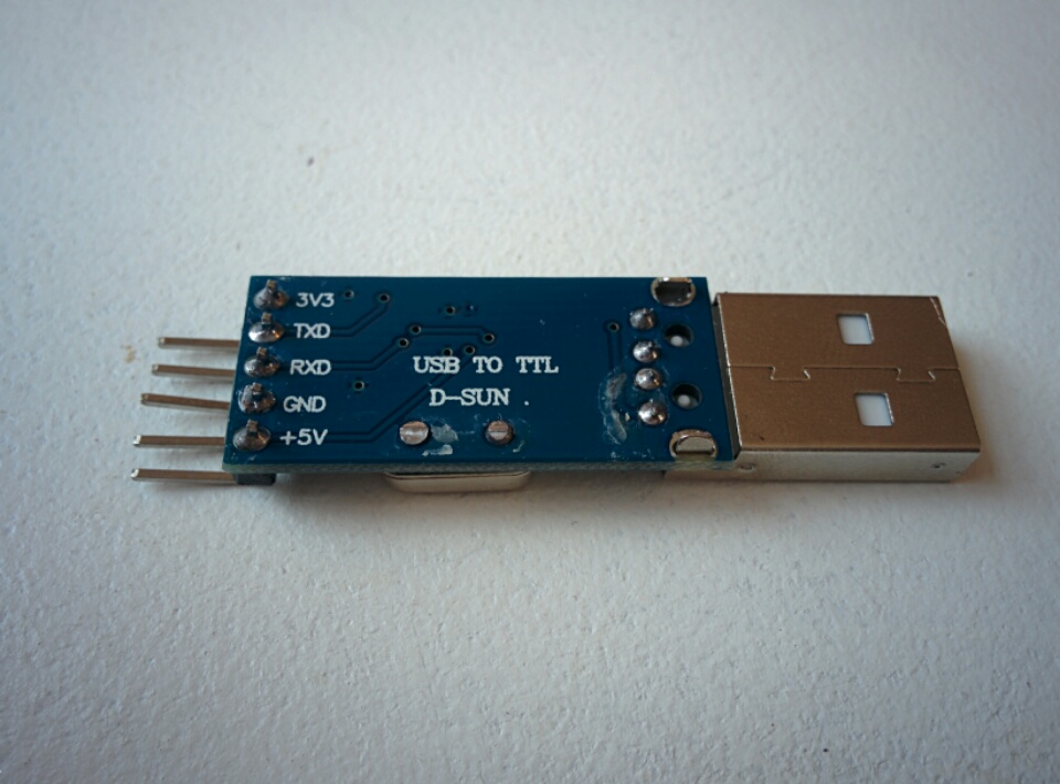
Prolific PL2303HX
Works, sometimes.
I honestly did not expect them to. Hilariously, these come shrink wrapped in plastic, because the USB plug support posts aren’t even soldered!
These are probably counterfeit chips, too, but who knows? Also, they don’t really work in Windows, after Prolific disabled support for counterfeit devices (though sometimes I wonder how they even know).
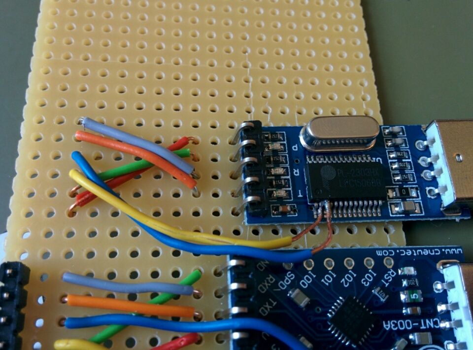
Thanks to Daniel for soldering the DTR and RTS wires onto the extremely thin SSOP pins. For great justice!
[30217.752502] usb 3-1.4: new full-speed USB device number 32 using ehci-pci
[30217.845449] usb 3-1.4: New USB device found, idVendor=067b, idProduct=2303
[30217.845454] usb 3-1.4: New USB device strings: Mfr=1, Product=2, SerialNumber=0
[30217.845457] usb 3-1.4: Product: USB-Serial Controller
[30217.845459] usb 3-1.4: Manufacturer: Prolific Technology Inc.
[30217.845884] pl2303 3-1.4:1.0: pl2303 converter detected
[30217.847596] usb 3-1.4: pl2303 converter now attached to ttyUSB1
Bus 003 Device 032: ID 067b:2303 Prolific Technology, Inc. PL2303 Serial Port
$ ./esptool.py read_mac
esptool.py v1.0.2-dev
Connecting...
MAC: 5c:cf:7f:07:8e:cd

$ ./esptool.py chip_id
esptool.py v1.0.2-dev
Connecting...
Chip ID: 0x00078ecd

$ ./esptool.py flash_id
esptool.py v1.0.2-dev
Connecting...
Manufacturer: e0
Device: 4016

$ ./esptool.py read_flash 0x0 0x80000 x.bin
esptool.py v1.0.2-dev
Connecting...
Running Cesanta flasher stub...
Reading 524288 @ 0x0... 524288 (100 %)
Read 524288 bytes at 0x0 in 49.9 seconds (84.0 kbit/s)...

$ ./esptool.py write_flash 0x0 x.bin
esptool.py v1.0.2-dev
Connecting...
Running Cesanta flasher stub...
Flash params set to 0x0000
Writing 524288 @ 0x0... 524288 (100 %)
Wrote 524288 bytes at 0x0 in 46.1 seconds (90.9 kbit/s)...
Leaving...
Silicon Labs CP2102 (black PCB)
Works.

Silicon Labs CP2102 (red PCB)
Works.
[ 7727.919777] usb 2-1: new full-speed USB device number 4 using xhci_hcd
[ 7728.049611] usb 2-1: New USB device found, idVendor=10c4, idProduct=ea60
[ 7728.049616] usb 2-1: New USB device strings: Mfr=1, Product=2, SerialNumber=3
[ 7728.049619] usb 2-1: Product: CP2102 USB to UART Bridge Controller
[ 7728.049621] usb 2-1: Manufacturer: Silicon Labs
[ 7728.049623] usb 2-1: SerialNumber: 0001
[ 7729.078772] usbcore: registered new interface driver usbserial
[ 7729.078985] usbcore: registered new interface driver usbserial_generic
[ 7729.079148] usbserial: USB Serial support registered for generic
[ 7729.083795] usbcore: registered new interface driver cp210x
[ 7729.083830] usbserial: USB Serial support registered for cp210x
[ 7729.083862] cp210x 2-1:1.0: cp210x converter detected
[ 7729.084803] usb 2-1: cp210x converter now attached to ttyUSB0
Bus 002 Device 007: ID 10c4:ea60 Cygnal Integrated Products, Inc. CP210x UART Bridge / myAVR mySmartUSB light
$ ./esptool.py read_flash 0x0 0x80000 x.bin
esptool.py v1.0.2-dev
Connecting...
Running Cesanta flasher stub...
Reading 524288 @ 0x0... 524288 (100 %)
Read 524288 bytes at 0x0 in 60.8 seconds (69.0 kbit/s)...

$ ./esptool.py write_flash 0x0 x.bin
esptool.py v1.0.2-dev
Connecting...
Running Cesanta flasher stub...
Flash params set to 0x0000
Writing 524288 @ 0x0... 524288 (100 %)
Wrote 524288 bytes at 0x0 in 45.5 seconds (92.3 kbit/s)...
Leaving...
Silicon Labs CP2104 (blue PCB)
Works!
After modifying the DTR line to bypass the capacitor as suggested by comments from 0xPIT, this adapter works as expected.
Doesn’t work.
Persistent errors on DTR line:
$ python esptool.py --port /dev/ttyUSB0 chip_id esptool.py v1.0.2-dev Connecting... Traceback (most recent call last): File "esptool.py", line 1214, inmain() File "esptool.py", line 1124, in main esp.connect() File "esptool.py", line 159, in connect self._port.setDTR(False) File "/usr/local/lib/python2.7/dist-packages/serial/serialutil.py", line 547, in setDTR self.dtr = value File "/usr/local/lib/python2.7/dist-packages/serial/serialutil.py", line 411, in dtr self._update_dtr_state() File "/usr/local/lib/python2.7/dist-packages/serial/serialposix.py", line 607, in _update_dtr_state fcntl.ioctl(self.fd, TIOCMBIC, TIOCM_DTR_str) IOError: [Errno 5] Input/output error $ python esptool.py --port /dev/ttyUSB0 chip_id esptool.py v1.0.2-dev Connecting... A fatal error occurred: Failed to connect to ESP8266 $ python esptool.py --port /dev/ttyUSB0 flash_id esptool.py v1.0.2-dev Connecting... Traceback (most recent call last): File "esptool.py", line 1214, in main() File "esptool.py", line 1124, in main esp.connect() File "esptool.py", line 159, in connect self._port.setDTR(False) File "/usr/local/lib/python2.7/dist-packages/serial/serialutil.py", line 547, in setDTR self.dtr = value File "/usr/local/lib/python2.7/dist-packages/serial/serialutil.py", line 411, in dtr self._update_dtr_state() File "/usr/local/lib/python2.7/dist-packages/serial/serialposix.py", line 607, in _update_dtr_state fcntl.ioctl(self.fd, TIOCMBIC, TIOCM_DTR_str) IOError: [Errno 5] Input/output error
[12903.595812] usb 2-1: new full-speed USB device number 12 using xhci_hcd
[12903.725411] usb 2-1: New USB device found, idVendor=10c4, idProduct=ea60
[12903.725416] usb 2-1: New USB device strings: Mfr=1, Product=2, SerialNumber=3
[12903.725418] usb 2-1: Product: CP2104 USB to UART Bridge Controller
[12903.725420] usb 2-1: Manufacturer: Silicon Labs
[12903.725422] usb 2-1: SerialNumber: 0100ACEA
[12903.726485] cp210x 2-1:1.0: cp210x converter detected
[12903.727140] usb 2-1: cp210x converter now attached to ttyUSB0
Bus 002 Device 012: ID 10c4:ea60 Cygnal Integrated Products, Inc. CP210x UART Bridge / myAVR mySmartUSB light
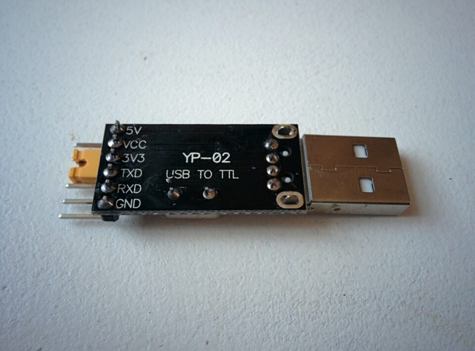
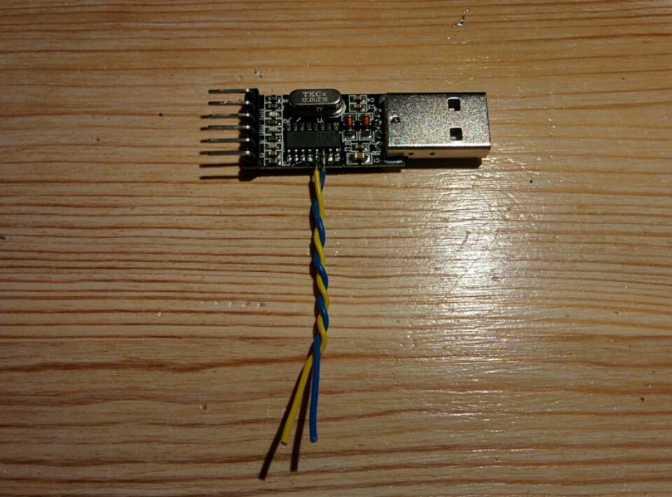
WinChipHead CH340G
Works!
These things are so ridiculously cheap. They’re normally covered in a shrink-wrap plastic tube, which is because the two USB support pins aren’t even soldered!
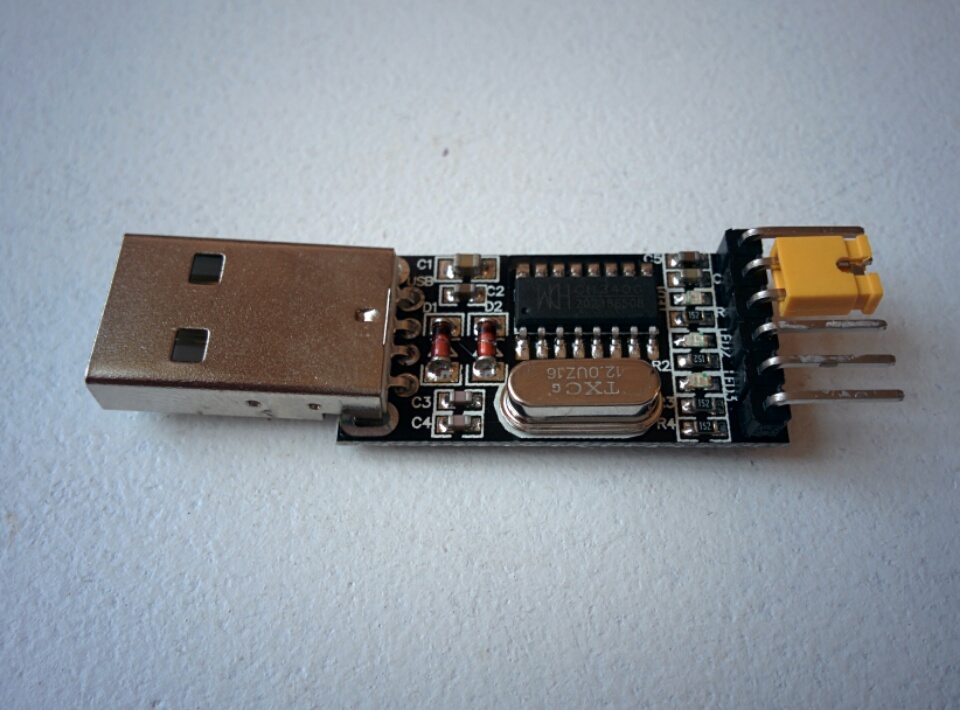
These are more work, you have to wire the DTR / RTS lines on the SOP package.
[11337.449533] usb 2-1: new full-speed USB device number 6 using xhci_hcd
[11337.578783] usb 2-1: New USB device found, idVendor=1a86, idProduct=7523
[11337.578788] usb 2-1: New USB device strings: Mfr=0, Product=2, SerialNumber=0
[11337.578790] usb 2-1: Product: USB2.0-Serial
[11338.602146] usbcore: registered new interface driver ch341
[11338.602511] usbserial: USB Serial support registered for ch341-uart
[11338.602547] ch341 2-1:1.0: ch341-uart converter detected
[11338.604752] usb 2-1: ch341-uart converter now attached to ttyUSB0
Bus 002 Device 006: ID 1a86:7523 QinHeng Electronics HL-340 USB-Serial adapter
$ ./esptool.py read_flash 0x0 0x80000 x.bin
esptool.py v1.0.2-dev
Connecting...
Running Cesanta flasher stub...
Reading 524288 @ 0x0... 524288 (100 %)
Read 524288 bytes at 0x0 in 50.8 seconds (82.5 kbit/s)...

$ ./esptool.py write_flash 0x0 x.bin
esptool.py v1.0.2-dev
Connecting...
Running Cesanta flasher stub...
Flash params set to 0x0000
Writing 524288 @ 0x0... 524288 (100 %)
Wrote 524288 bytes at 0x0 in 45.5 seconds (92.3 kbit/s)...
Leaving...